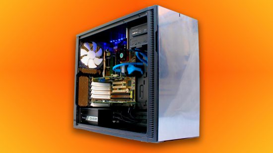
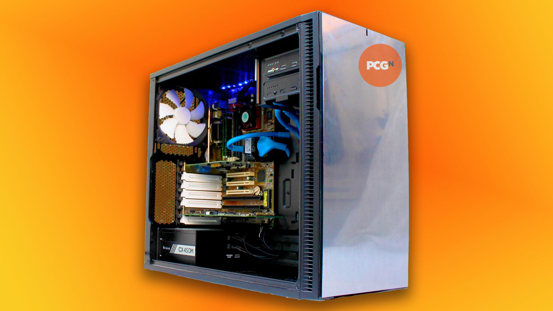
In this guide, we’ll show you how to build a retro gaming PC, based on original hardware from the 1990s, with a few modern touches. It can run DOS games and early Windows games, but it’ll also look good doing it. We’re using a recent case and PSU, as well as solid state storage, but we’re also using a Sound Blaster 16, a Pentium MMX, and an old PCI graphics card.
Why build a retro gaming PC?
There’s no doubt that DOSBox is a seriously powerful virtual emulator that works brilliantly. However, it doesn’t quite tick all the boxes. If you want to put an actual hardware synthesizer card in your PC, and hear it play music in games in real time, with the option to expand it with a wavetable daughterboard, then you need the original hardware.
If you want to boot to a DOS prompt and know that your computer is running the software natively, without emulation, then you’ll need a real 1990s PC. In all honesty, it might make little difference to the end result compared with an emulator, but it’s a fun project, and it also gives you an understanding of how old PC hardware works, which you don’t always get from an on-screen DOS emulator.
If you’ve ever wondered what it was like to use a PC from the old days, and fancy having a dabble with old hardware, but don’t know your AT from your AT-AT, then this guide is for you. In fact, even if you don’t want to buy a load of overpriced ancient hardware in order to construct an obsolete gaming machine (and we won’t judge you for that, much), we’ll give you a grounding in how the PC has changed in some ways, but not in others, and help you understand the foundation on which today’s PCs are built.
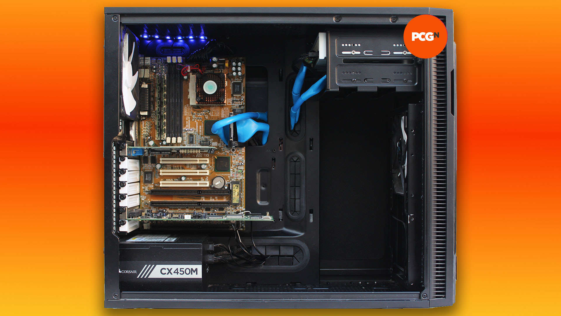
Mixing old and new components in a retro gaming PC
The idea behind our retro rig is to combine the best of the old world with the perks of the new world. While there are parts of the legacy PC hardware era we miss, there are others that we’re very glad have been consigned to the great silicon scrapheap in the sky. There was no way we were going to use a 1990s case, for example.
As well as having that horrible off-white color, which yellowed over time, early PC cases were often badly designed and built. There was nearly always sharp metal on which you could easily scrape your knuckles, very little consideration given to cable routing, drive bays everywhere and the PSU would often be sat at the top.
We also wanted to avoid using an old hard drive. Mechanical hard drives can become unreliable after five years, let alone 25, plus they’re slow and noisy, so we wanted to use solid-state storage. However, we also wanted the flexibility to run any old software from charity shops and eBay, not to mention disks from the loft, and that means our system needs a CD-ROM drive and a floppy drive too.
Finally, PSUs have come an enormously long way since the 1990s. We have modular and semi-modular designs, wrapped/sleeved cables as standard, and the 80 Plus initiative has weeded out the flaky and inefficient PSU designs that were commonplace 25 years ago. So we’re using solid-state storage, a modern case, and a new PSU – in this case a Corsair CX450M. The rest of the core spec, however, is contemporary 1990s DOS hardware.
ISA and PCI slots
Your first priority when building a DOS gaming system is the motherboard. You want one with 16-bit ISA slots (long and usually black), so you can get the sound working properly. PCI sound cards were largely designed for Windows, rather than DOS, and while some of them have DOS drivers, it’s a faff trying to get them to work in all your games.
PCI sound cards also tend to make heavy use of the CPU, and don’t have all the required audio hardware on them, relying on the CPU to do some of the work. That’s fine if you have a Pentium III and Windows 98, but it’s rubbish for DOS gaming – an ISA card will have all the synthesizer hardware you need on it. However, it’s worth having a PCI slot for your graphics card.
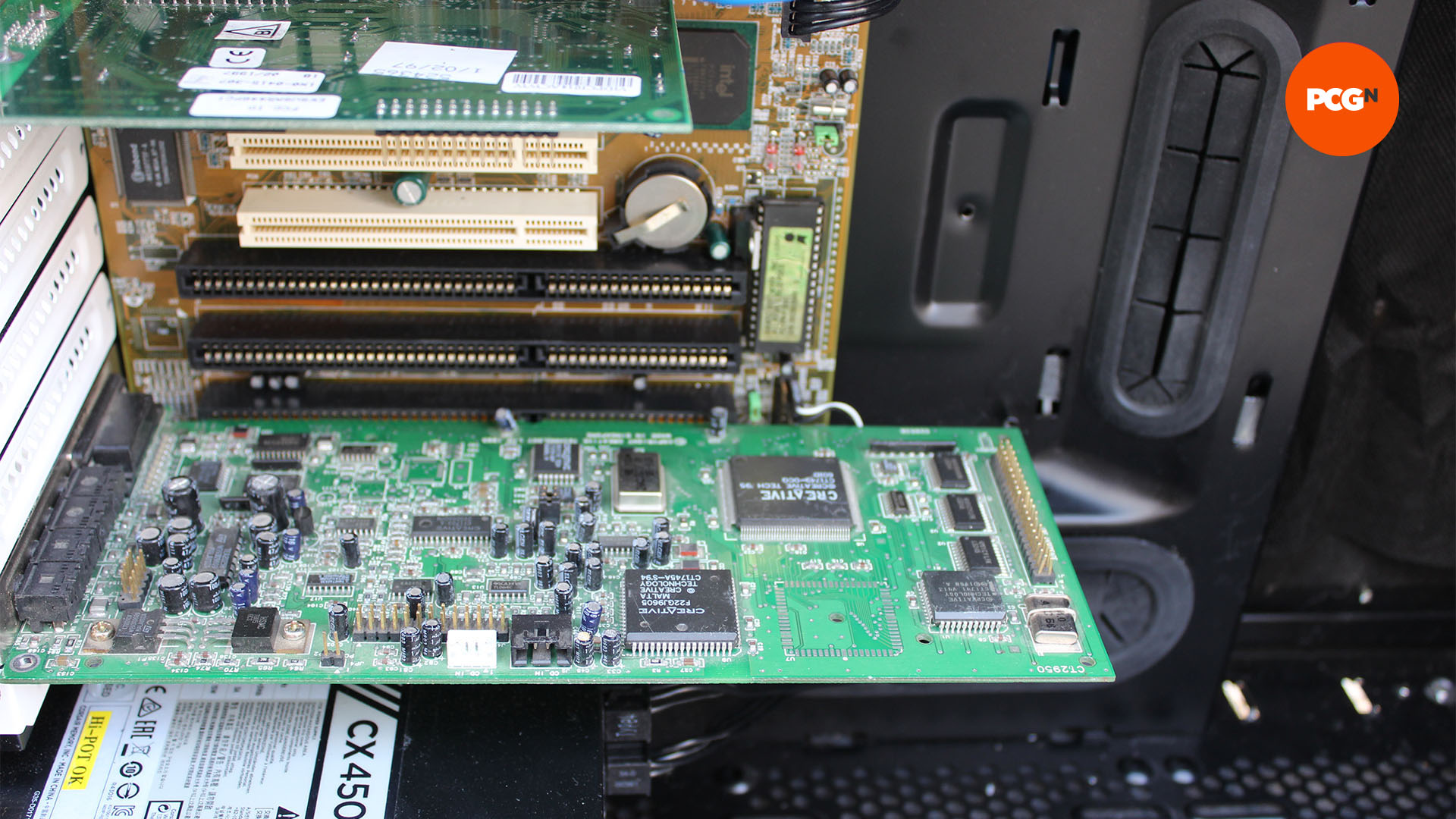
Some motherboards from the 1990s will also have VESA local bus slots, which look a bit like an ISA slot with a brown PCI slot on the end. You can install an ISA graphics card in these slots, but actual VESA local bus cards are generally expensive and hard to find these days. Ideally, look for a motherboard with a mix of both ISA and PCI slots – the latter are short, with a thin socket in the middle, and they’re usually white.
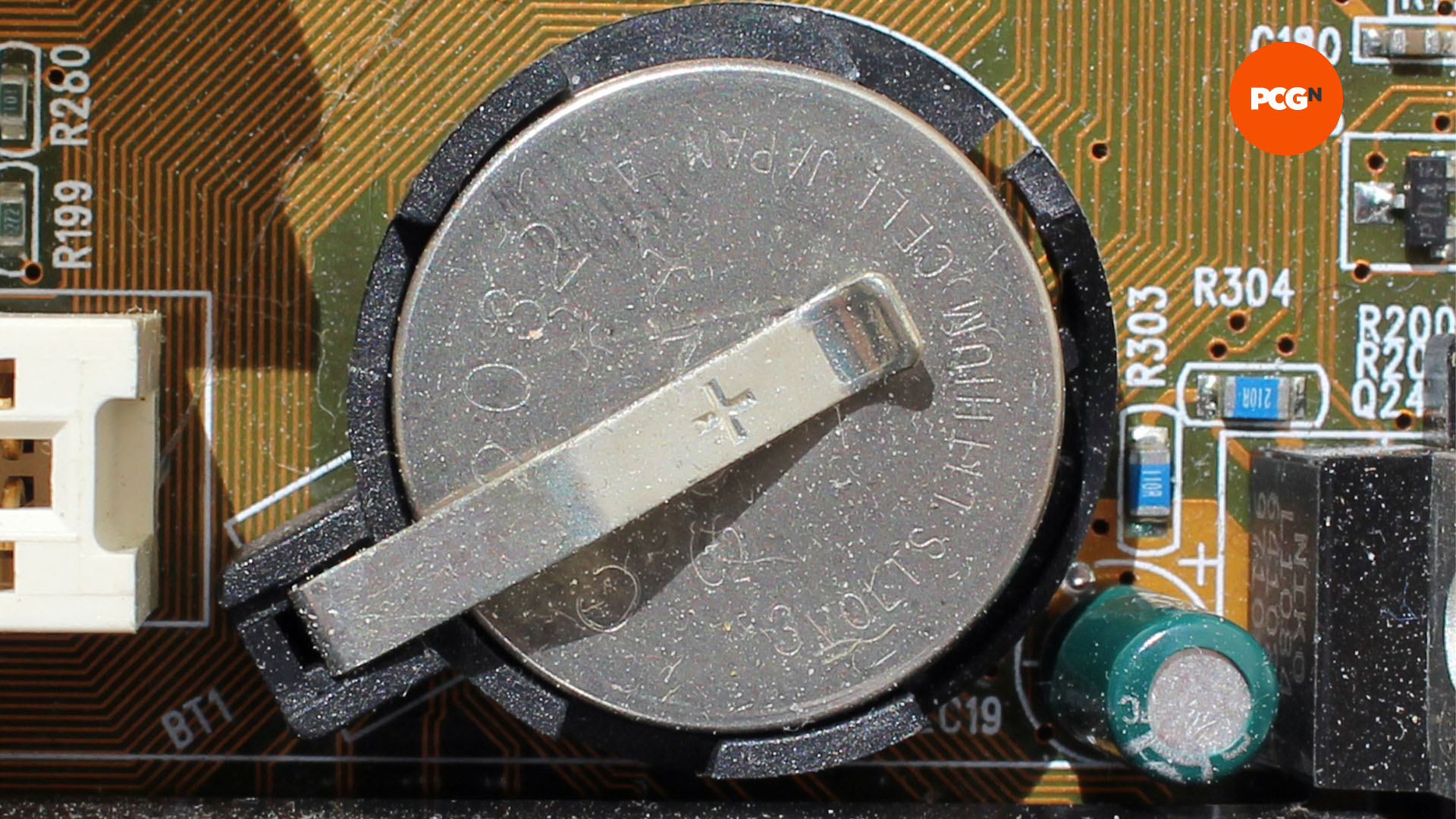
You also want a replaceable CMOS battery. These silver discs are a standard feature of today’s motherboards, but in the 1980s and 1990s, the CMOS battery was often soldered to the motherboard. This wasn’t a major issue at the time, as the batteries lasted for years, but decades later, these batteries have run dry, and you’ll now need a careful touch with a soldering iron to replace them.
The other crucial considerations for motherboards are their form factor and power socket. For starters, avoid any proprietary motherboard designs. These were often found in the PCs from big brands at the time, such as Compaq, Hewlett-Packard and so on. These PCs were fine in themselves, but they severely lacked flexibility, as they often had proprietary power connectors and their I/O ports would be positioned in non-standard locations, to fit with the custom case designs.
Meanwhile, in the world of DIY PCs and independent system builders, there were two main standards of motherboard – AT and ATX, with the latter coming later. AT was a firm favorite among enthusiasts, as it maintained compatibility with older cases. If you bought an AT 386 system, you could replace the motherboard with a Super Socket 7 AT motherboard many years later.
The only port soldered to a standard AT motherboard was a large 5-pin DIN socket for connecting a keyboard. Any other ports would be connected via ribbon cables, using expansion slot backplates or cut-outs on the back of the case.
The power supply socket was also a bit of an oddity, with the PSU having two plugs that needed lining up together. There was no way to turn off an AT PC with software either, so there would be a hard push-in/push-out switch trailing off the PSU.
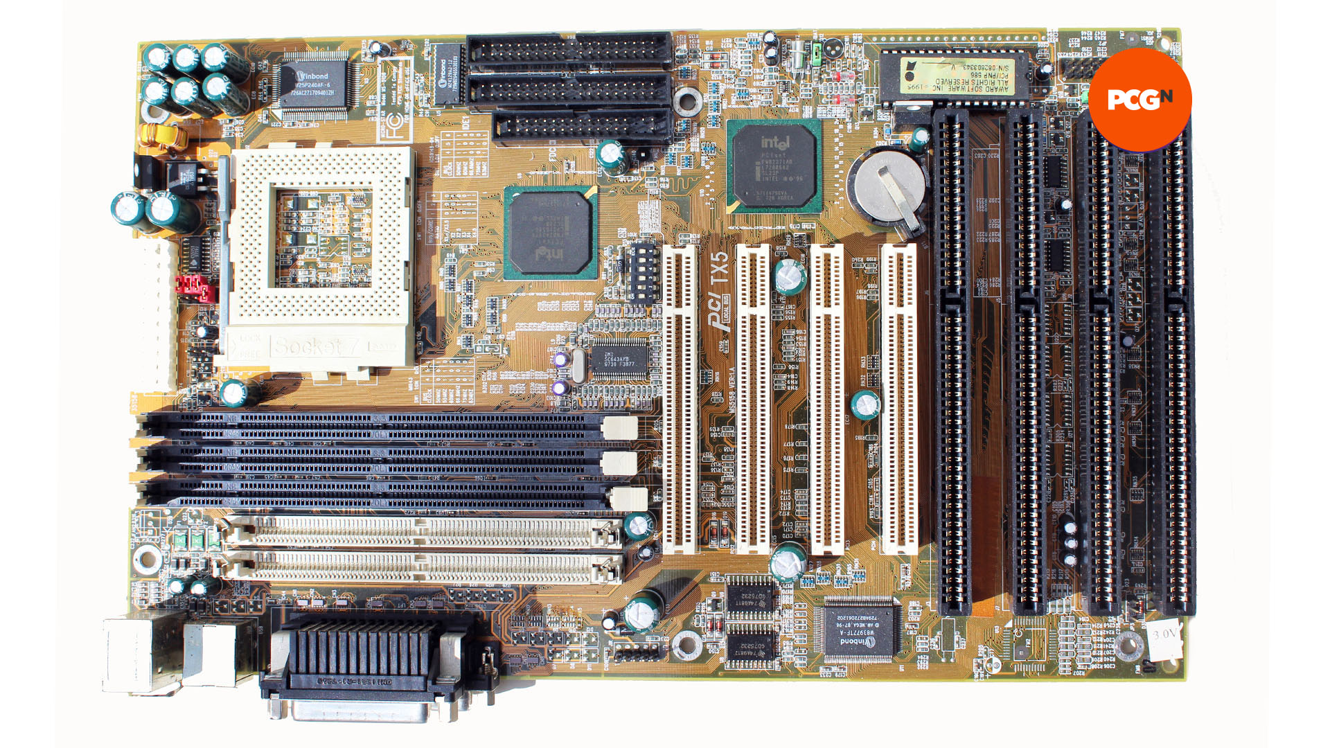
ATX introduced the motherboard power socket that we still use today, albeit with 20 pins rather than 24, as well as the ability to turn off the system with software, so you could tap a simple power button rather push in a hard switch. The ATX standard also introduced the standard motherboard length and I/O backplate design you see on motherboards now.
You can avoid most of the pitfalls of incompatibility by simply opting for a motherboard with an ATX form factor and power socket. In our case, we’ve gone for an MSI MS-5158, an ATX Socket 7 motherboard based on the Intel Triton TX chipset – it has PCI and ISA slots, and a replaceable CMOS battery, plus it supports a wide range of CPUs, from early Intel Pentiums to the later MMX chips, as well as AMD’s K6 processors.
Retro gaming PC PSU
Your power supply and its connectors are also a consideration. You should be able to use a new one, rather than scouting around for an old 1990s one – just make sure that the main ATX connector ( 24-pin on the latest designs) can be separated into two parts – the large 20-pin part will connect straight into the socket on an old ATX motherboard.
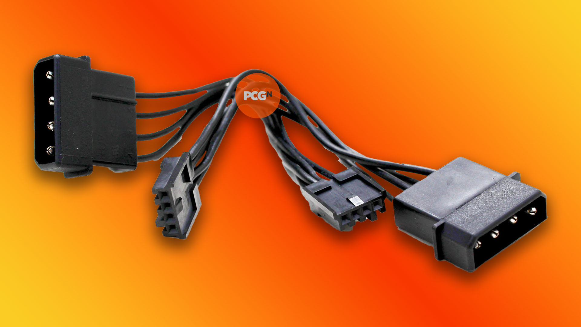
Secondly, you’ll need plenty of Molex connectors, plus a couple of floppy power connectors. Most PSUs have the former in some form, but the latter can be hard to find sometimes. Thankfully, you can get adaptor cables on eBay and Amazon, which go straight from a Molex connector to a floppy plug, and also ones that go from SATA power to Molex power. We bought a pair of black Corsair Molex-to-floppy adaptors on eBay.
Retro gaming PC CPU
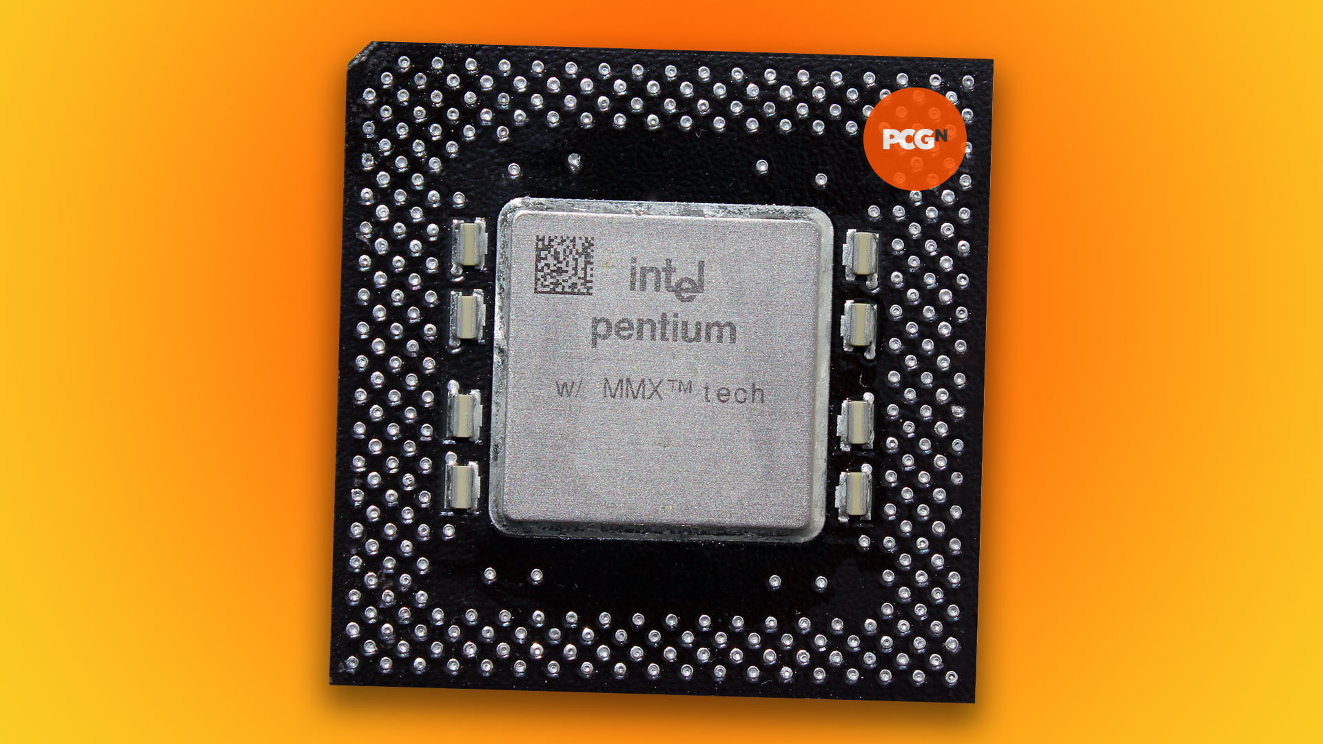
The CPU is your next consideration, and there’s a huge range of options here. We suggest avoiding Cyrix CPUs, as their poor floating-point performance will make them struggle in games such as Quake. An AMD K6 or Intel Pentium will do the job fine. We’re using a 166MHz Pentium MMX, which is overkill for most of the games we’ll be running on our system, but that hardly matters when you can pick them up for $15 now.
You could also use a Slot 1 Pentium II or Celeron system, as long as it has ISA slots for your sound card. These systems were much more geared towards 32-bit computing than their Socket 7 predecessors, and they won’t give you any advantage over Socket 7 CPUs in DOS games, but they will work.
Likewise, an AGP graphics card will boot into DOS, but there’s no advantage to using one over a PCI card, as there will be no DOS 3D drivers. There are a few considerations when buying a graphics card for DOS though.
Firstly, the minimum you want for DOS games is a 256KB VGA card, which will enable you to run games at 320 x 240 (or 320 x 200 ) with 256 colors, and you can step up to 640 x 480 with 16 colors. Having a 512KB card will enable you to get 256 colors at 640 x 480, and stepping up to 1MB will even enable 16-bit color (over 64,000 colors) at 640 x 480, or 256 colors at 800 x 600.
Virtually no DOS games support the latter two modes, but they’re handy if you want to have a play with Windows 3.1. If you do want to run Windows 3.1 on your retro system (which will open you up to some other games, such as Civilization II), make sure there’s a driver available for your graphics card. A PCI graphics card will also be quicker in Windows than an ISA one, making for a more responsive experience. We’ve chosen a 1MB PCI Cirrus Logic 5446, which covers all our bases – you can still pick them up cheaply on eBay.
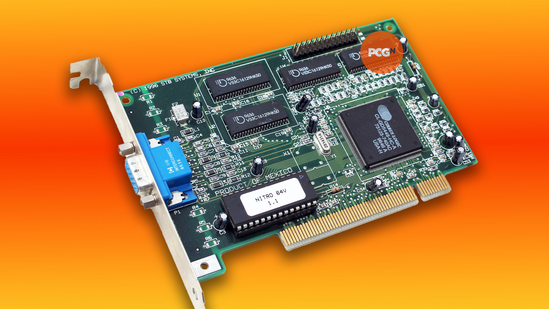
You’ll also need a supporting monitor with an analog 15-pin VGA input, or an HDMI or DVI input with an active adaptor – a passive cable won’t work here, as you need to convert the analog signal to digital, so do your research before purchasing.
If you want the full retro experience, you could even pick up an old CRT monitor, but we’re just plugging our machine into a 4K iiyama monitor in the lab, which has a 15-pin VGA input, as well as the ability to change the aspect ratio to 4:3 in the OSD menu. You’ll want the latter feature if you don’t want your games to look weirdly stretched.
Retro gaming PC SIMMs and DIMMs
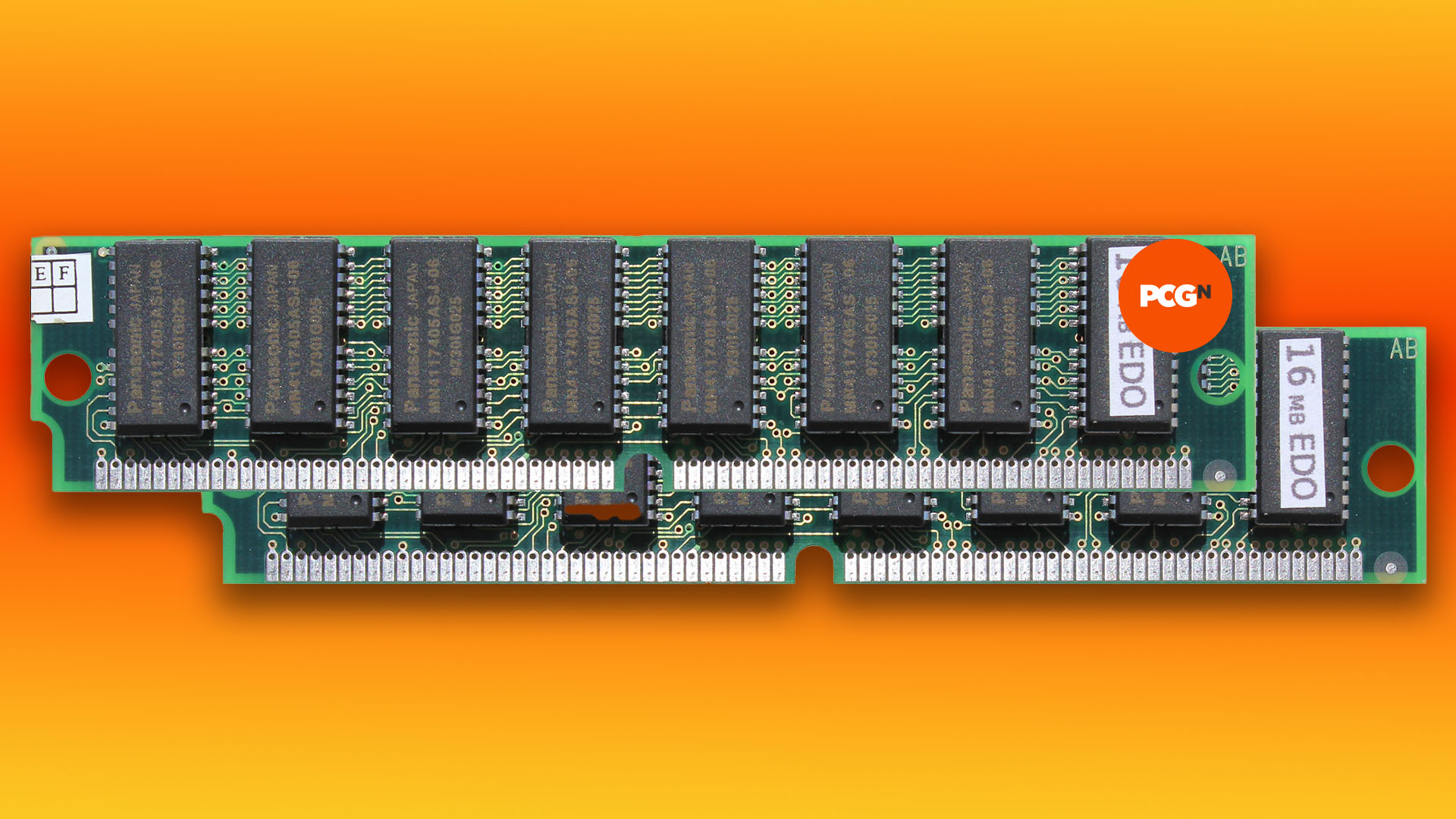
Next up is memory, and you may have two options here – 72-pin SIMMs or 168-pin DIMMs. Single inline memory modules (SIMMs) need to be installed in pairs on Pentium systems, although you could install them singularly on some earlier 486 PCs. You’ll have a choice of fast page non-parity or EDO memory – either should work fine, but EDO will be slightly quicker.
Meanwhile, 168-pin dual-inline memory modules (DIMMs) come with either EDO or SDRAM chips (the latter is quicker), and it’s fine to install them singularly rather than in pairs, although you won’t be able to mix DIMMs and SIMMs together. SDRAM DIMMs also come in a variety of clock speeds to match the front side bus.
As with today’s memory, the fastest DIMMs can slow down to lower clock speeds, so you may as well buy 100MHz (or even 133MHz) memory if you have the option. This will match the bus speed of later AMD K6-II and Pentium II motherboards, and slow down to 66MHz on older systems. For our DOS and Windows 3.1 system, 32MB is plenty, and our CPU uses a 66MHz front side bus, so we’re just going with a pair of 16MB EDO 72-pin SIMMs.
Solid state storage on a retro PC
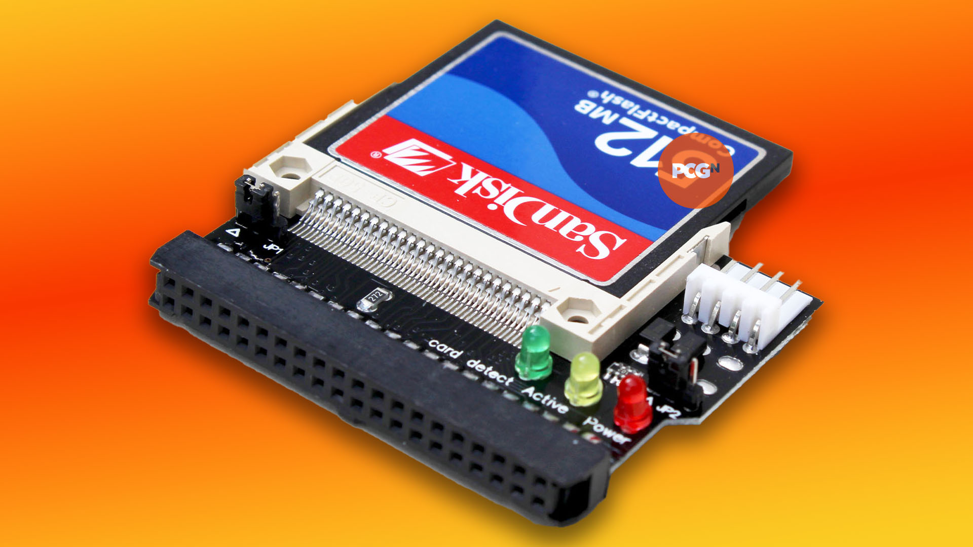
The idea of running your whole PC on solid state storage was a mere fantasy back in the 1990s, but you can easily use flash memory for your main storage system on an old PC now. There are various methods, but we’re going to use a CompactFlash adaptor that plugs into an IDE socket and requires a floppy power connector – it cost us just $5.99 on eBay. There are also options that plug into ISA slots, but the IDE method makes for a system that’s easy to set up for booting in the BIOS.
CompactFlash is readily available in a variety of capacities, and its removable nature means you can easily have a few flash cards to boot your system with different options. What’s more, you can easily plug a Compact Flash card into a USB card reader, and transfer files from another PC to it, which is much easier than mucking about with slow and unreliable floppy disks.
We’re using a 512MB card, but you can go higher. DOS runs on a FAT16 (not FAT32 ) file system, which means you’re limited to using no more than 2GB for a single drive, although you can also partition a larger flash card into multiple 2GB drives with different letters.
Our other two storage devices are an IDE CD-ROM drive and a 3.5-inch floppy drive, which will connect directly to the motherboard’s IDE and floppy controller ports. You’ll need cables to attach both of these devices, which are commonly available in ribbon format, but in the early 2000s, some manufacturers started bunching the wires all together to make ‘rounded’ IDE and floppy cables, so they take up less space. You can still buy these new, and we’re using some blue ones here.
Retro gaming PC case
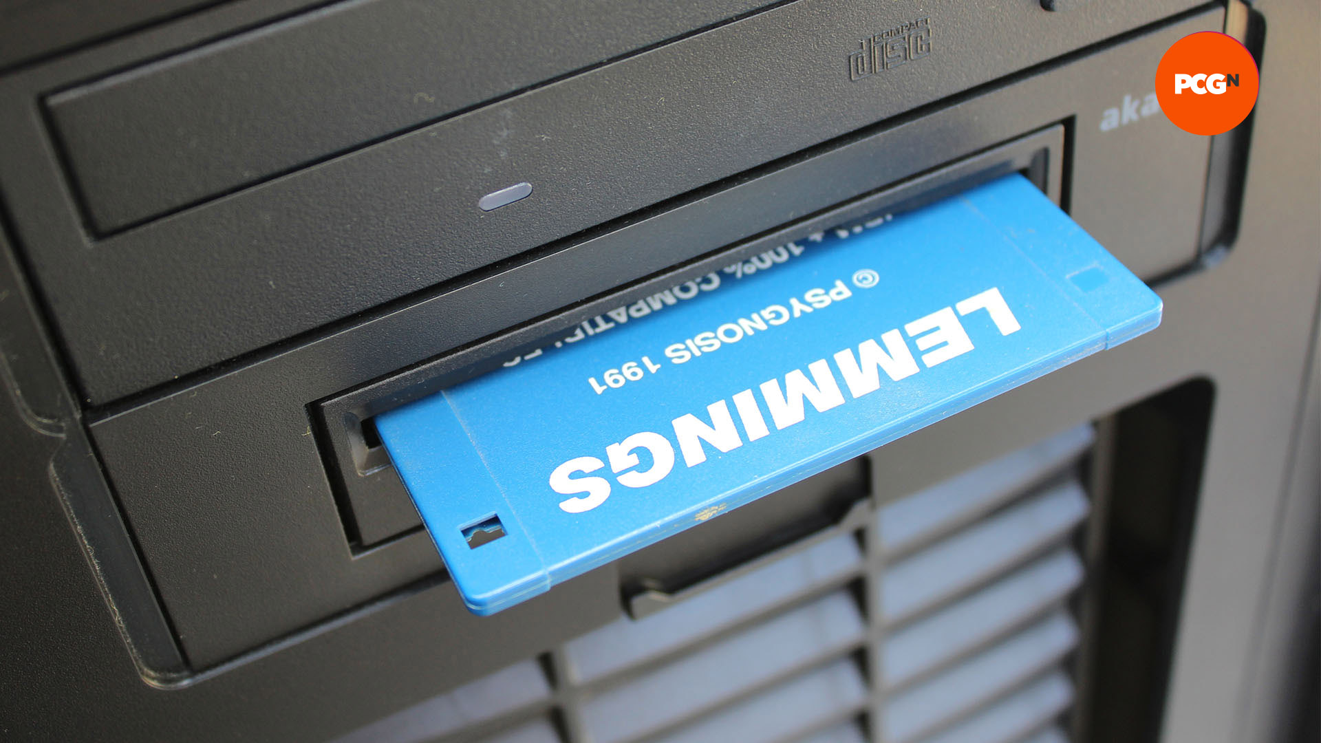
As we mentioned earlier, you should be able to install an old ATX motherboard into a new ATX case, but if you want to run software from the original media, it will also need front-facing drive bays. You’ll need a 5.25-inch bay for a CD-ROM drive, and a bay for a 3.5-inch floppy drive if you want that too. A dedicated 3.5-inch bay can be used for the latter, or you can get a 3.5-to-5.25-inch adaptor to put a floppy drive in a 5.25-inch drive bay.
We’re using a Fractal Design Define R5, which we had spare in the lab and has two 5.25-inch bays (we’re using an Akasa adaptor to install the floppy drive in a 5.25-inch bay), but there are other new cases that will do the job. The latest Fractal Design Define 7 has one 5.25-inch bay, for example, and the larger XL model has two 5.25-inch bays. The Fractal Design Focus G also gives you two-front-facing 5-25-inch bays, as does the Pure Base 600 from be quiet!
Retro gaming PC keyboard and mouse
If you have an old ATX motherboard, the rear I/O panel will likely have a pair of 9-pin serial ports (usually used for mice and external modems), a 25-pin parallel port (usually used for printers, but also some scanners and storage devices) and a pair of PS/2 ports (small 5-pin DIN sockets) – one for a keyboard and one for a mouse. You may even have USB ports, but these are useless for DOS.
We recommend using the PS/2 ports for your keyboard and mouse. PS/2 is quicker than serial, and there’s a decent range of PS/2 kit available, including optical mice (no one wants to return to using analog ball mice again, however nostalgic they are!)
You can even get some modern USB keyboards and mice working with old PS/2 ports via adaptors, but you’ll need to do your research. A USB peripheral will need to internally support the PS/2 protocol in order for it to work over a USB adaptor, and many of them don’t.
With a bit of help from Google, you should be able to find out if you can use your USB keyboard or mouse with a PS/2 adaptor. If not, you can buy second-hand PS/2 peripherals cheaply on eBay – it’s not as if you’re going to need a 4,000dpi sensor to play The Secret of Monkey Island, or even Doom for that matter.
Retro gaming PC sound cards
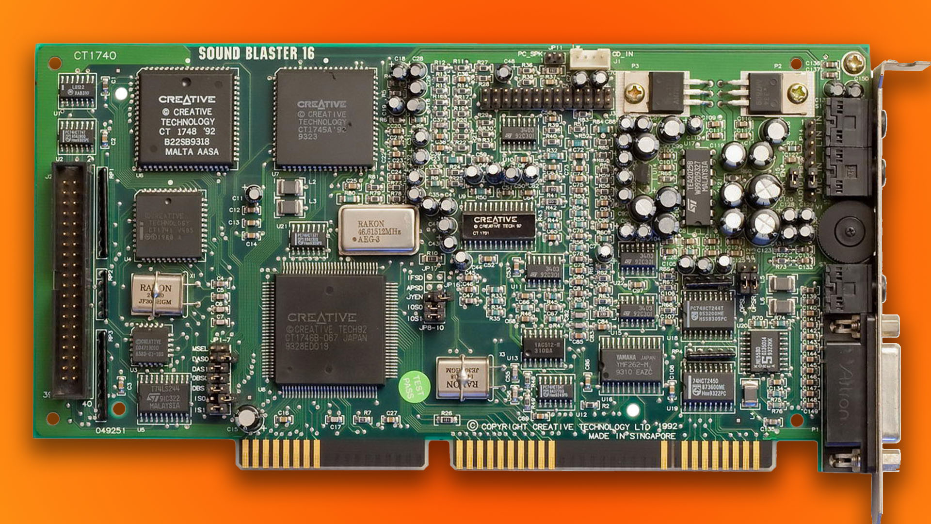
Finally, we come to the sound card. As we mentioned earlier, you want a 16-bit ISA sound card for DOS. The basic standard for DOS games is the Creative Sound Blaster Pro, which combines FM synthesis for music with the ability to play back 8-bit sampled sound – it’s great for a game such as Doom, so you get music and demon growls, gunshots and explosions. It’s also compatible with the first Ad-Lib products, which provided FM synthesis (but no sampled sounds) and are supported in quite a few DOS games, particularly early ones.
There are plenty of non-Creative 16-bit ISA cards that have Sound Blaster Pro compatibility and can be picked up quite cheaply – just make sure you can get the drivers for them. We’re using a Creative Sound Blaster 16, which has full compatibility with the Sound Blaster Pro, and can also play and record 16-bit sound.
There are advantages to buying a better sound card, though, as you can massively improve the quality of the synthesizer music in some games. Creative’s AWE32 and AWE64 cards have much better synth sounds than the Yamaha OPL2/OPL3 FM synthesizer sounds used by most cards at the time. Again, Doom is a great example of a game that sounds much better with one of these cards.
Another alternative is to use the MIDI interface on the Sound Blaster 16. The early Sound Blaster 16 and AWE32 cards (but not the later ones) had a wavetable daughterboard connector, to which you can attach a secondary synthesizer card. If you can find a Yamaha DB50XG, the sounds are amazing, and there are plenty of other decent-sounding daughterboards too.
Once it’s plugged into the wavetable connector, your daughterboard will then just output its synthesizer sounds through the line out. This setup will only work on games that can play music data through the MPU-401 interface but quite a few do, and they’ll sound better for it.
You can also use the 15-pin joystick port on the back of the Sound Blaster 16 for MIDI, via a 2 x MIDI ( 5-pin DIN) to 15-pin cable, which you can buy on eBay. A popular external MIDI box at the time was the Roland MT-32, which is supported in some DOS games, including King’s Quest IV.
So you’ve got all your bits and pieces, and because we’re using an ATX case, PSU and motherboard, much of the build process is similar to making a custom PC now. However, there are a few key differences.
Motherboard jumpers and DIP switches
The first warning is that your motherboard’s BIOS will be very different from today’s user-friendly EFI systems, and even the BIOSes found on boards ten years ago. In fact, for the moment, forget about the BIOS, and instead look at the various jumpers and switches on your motherboard.
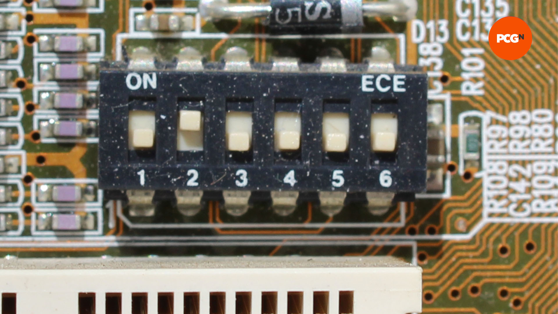
Firstly, there may be some DIP switches – plastic blocks featuring several little numbered on/off switches. Secondly, look for jumpers. Jumpers are small sets of pins with movable, conducting tops, which can be swapped around to connect pairs of pins, acting as switches.
Before you change anything, look for any tables printed on your motherboard that outline the position of the switches and what they mean. If you can’t find them, try to find your motherboard manual online, so you can see what all the switch settings mean. Getting this wrong can genuinely result in you accidentally overvolting or overclocking your hardware and cooking it. These could be perilous times for PC building!
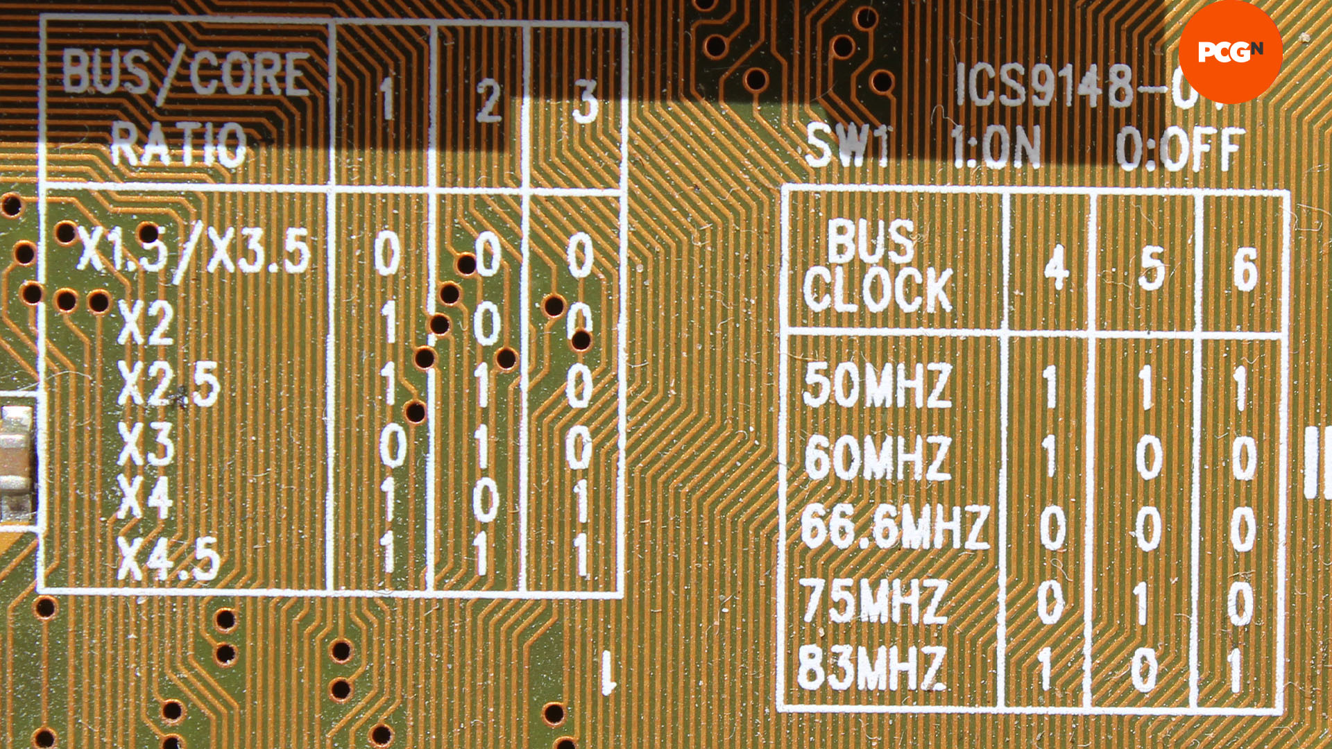
Now you need to set the switches and/or jumpers to meet the voltage, bus speed and multiplier for your CPU. In the case of our 166MHz Pentium MMX, that means a voltage of 2.8V, a 66MHz front side bus and a 2.5x multiplier. You’ll also need to check any jumpers or switches for the memory – some motherboards require a switch to be set to use SIMMs or DIMMs, or to set the memory speed. Triple-check all your switches and jumpers before you install your CPU.
Socket 7 CPU installation
Physically fitting the CPU is one area that hasn’t really changed over the past 25 years. In the early PC days, CPUs were sometimes soldered into motherboards, rather than using a sockets, and it wasn’t until the 486 era that zero-insertion force (ZIF) sockets really became a standard feature, but we’ve never looked back since.
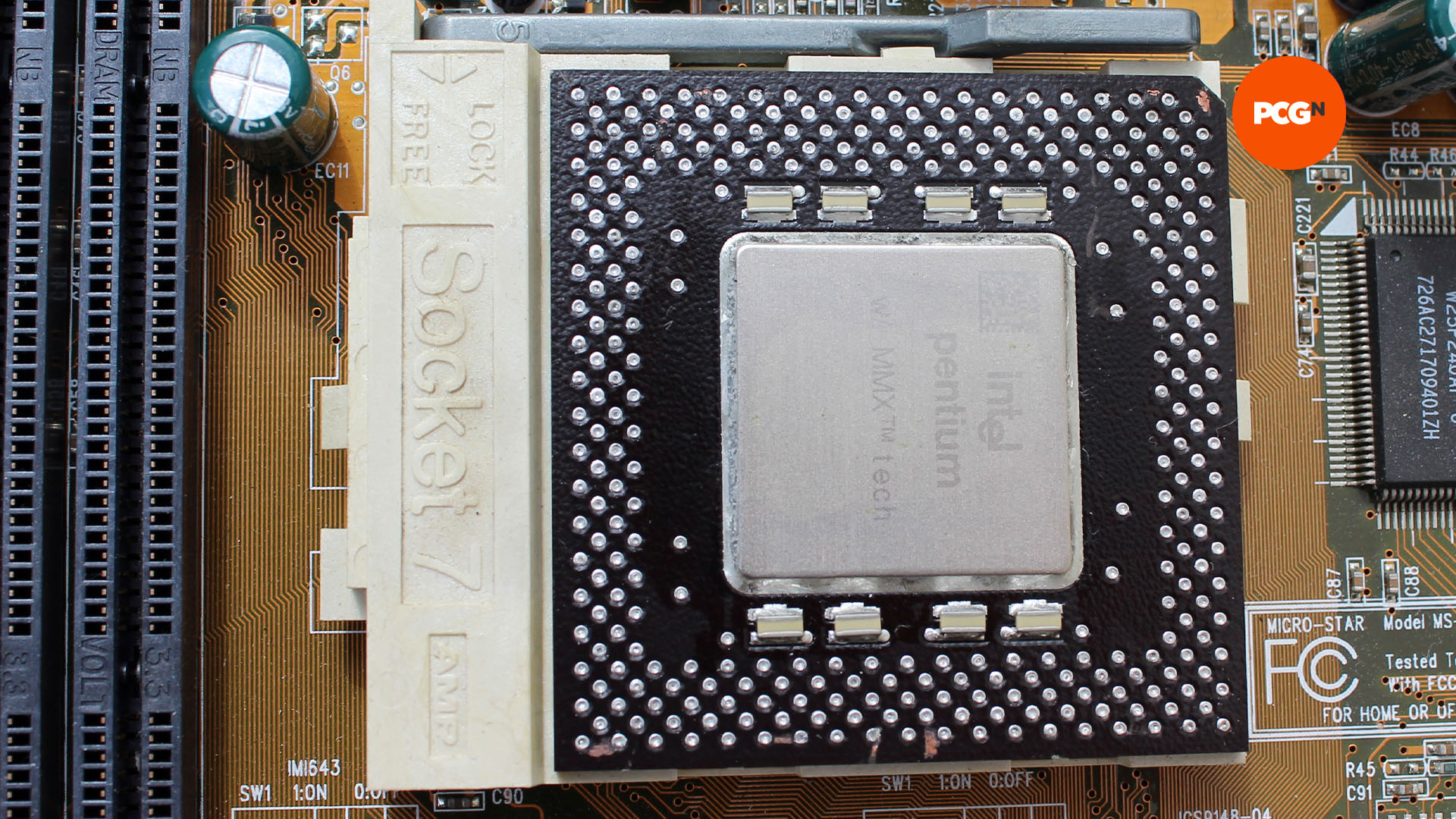
As such, installing our Pentium CPU is very similar to fitting a Socket AM4 Ryzen chip, such as the AMD Ryzen 7 5800X3D. You lift up the lever by the socket, and line up pin 1 on the CPU with pin 1 on the socket (denoted by a triangle shape). You can then slot the CPU into its socket and push down the lever to hold it in place.
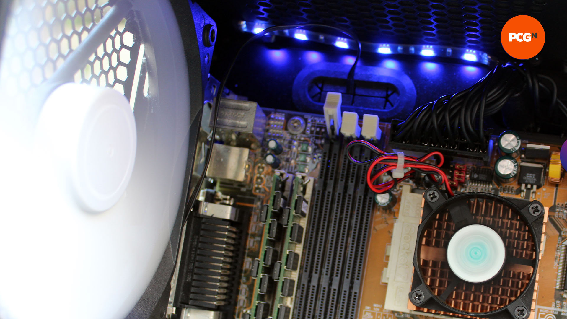
Next comes the CPU cooler, and this is an area that’s changed hugely over the past couple of decades. With a thermal design power (TDP) of just 13W, there’s no need for a massive CPU cooler on top of our Pentium MMX CPU, and sub-100MHz Pentiums technically don’t even need a fan.
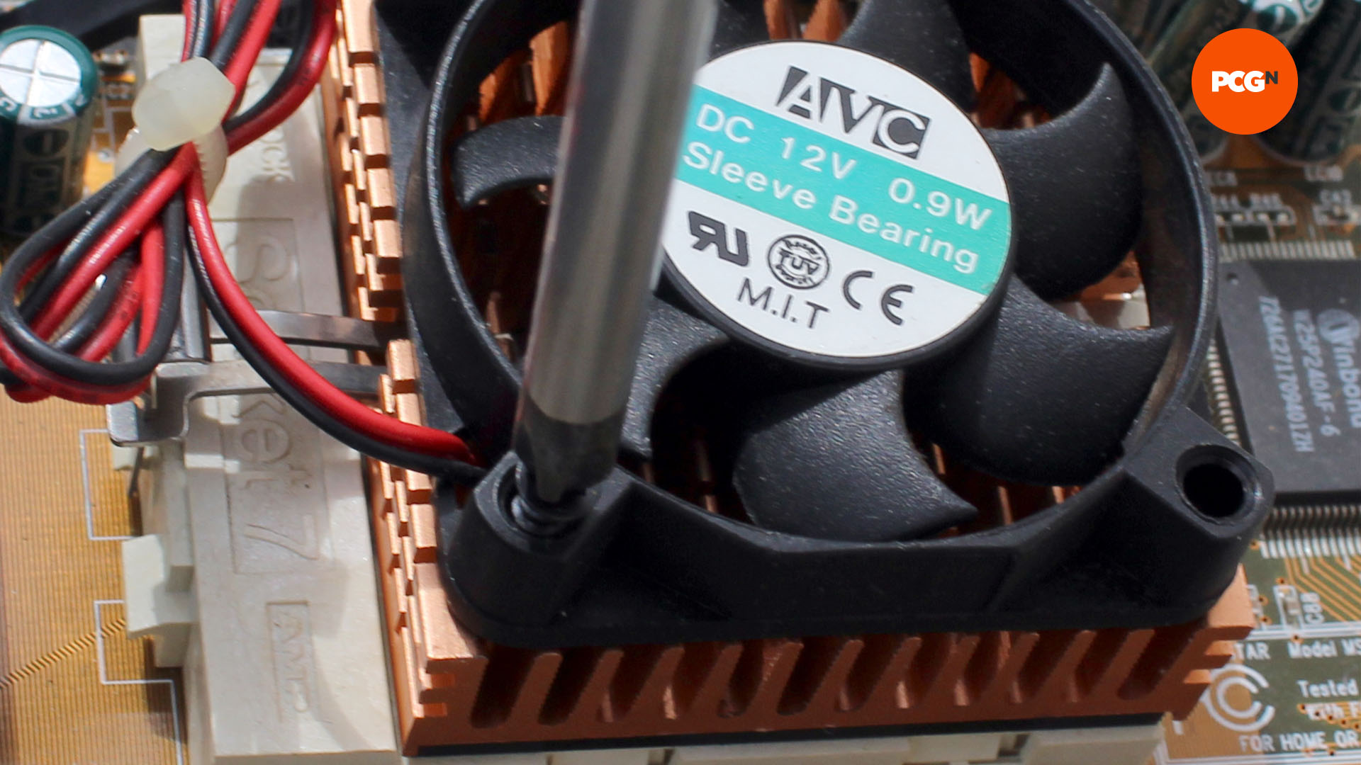
We’ve picked up a basic Socket 7 heatsink and fan on eBay. Apply a small blob of thermal paste in the middle of the CPU, then put the heatsink on top of it. You then simply clip the heatsink to the hooks on either side of the socket. You can then fit the fan (if it isn’t fitted already) and plug in its power cable – the power header is usually next to the CPU socket, but check your motherboard manual.
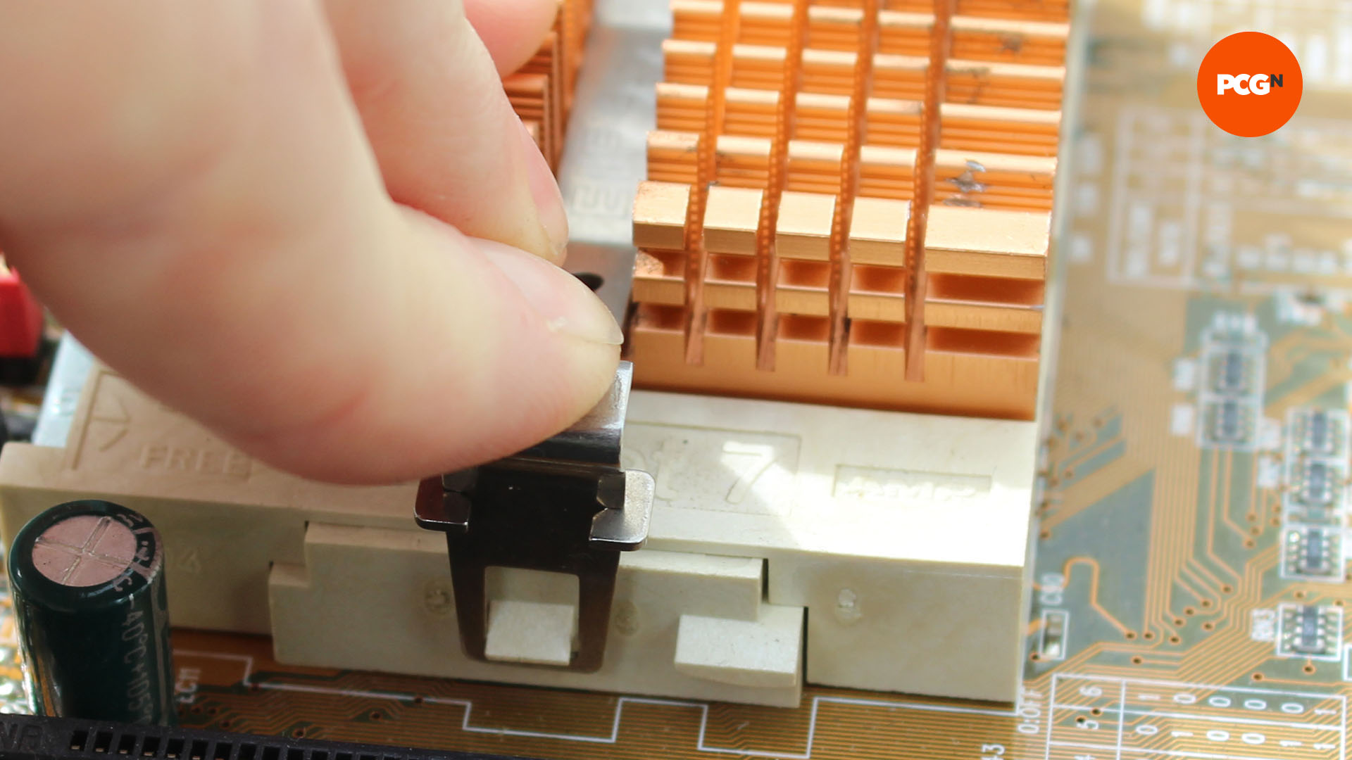
As a side note, you may notice that you can’t see the clips in the later pictures of our PC, which is because we got a bit carried away, and wanted to see if we could water-cool it for a laugh. It was all fun and games until the force of our custom retention clip for the waterblock ended up pulling a lug off one side of the socket. We ended up having to stick our heatsink to the CPU using thermal adhesive as a result. Don’t be like us – be sensible here.
How to install SIMMs
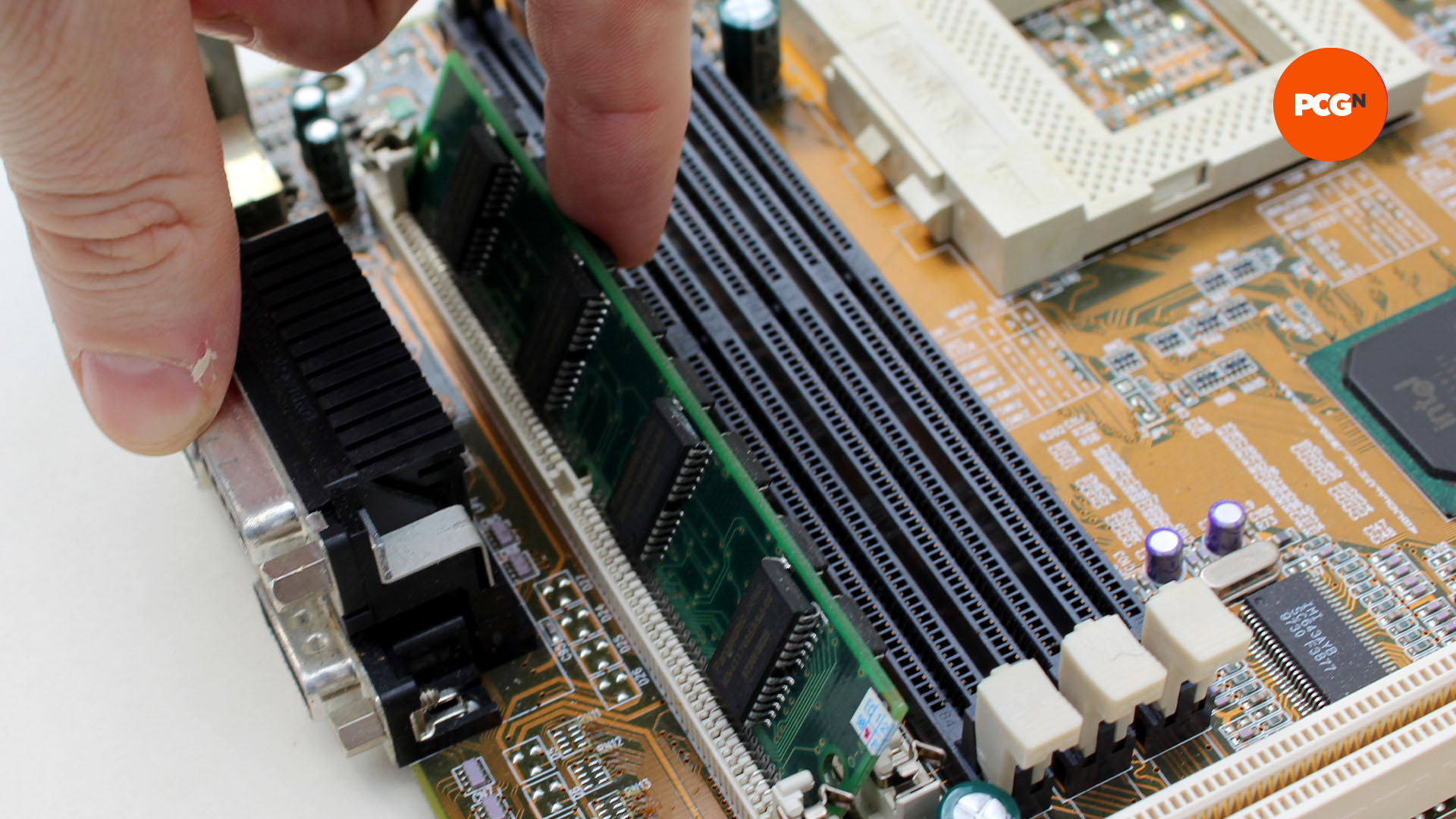
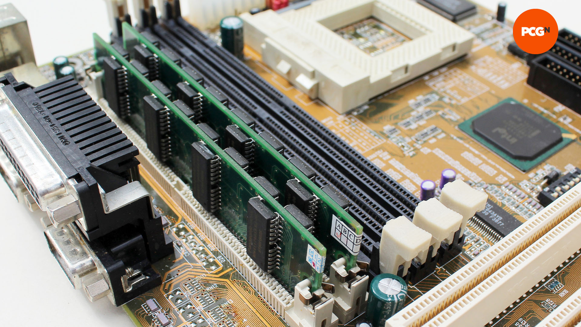
Next comes the memory. If you’re using a DIMM, the installation method is the same as today. Push back the clips, put the memory in the slot (it will only go in one way around) and push it down until the clips flip up to grip the memory. SIMMs are a little different, but still simple. To install a SIMM, insert it in the slot in an angle, as shown, then push it back to secure it in place.
Now is a good time to check your hardware works, so plug in your power supply’s 20-pin ATX connector (you may need to uncouple a block of four pins next to it) to the motherboard’s socket, install a graphics card and hook up a monitor.
You’ll then need to find the header for the power switch, which will be detailed in the motherboard manual, or may (if you’re lucky) be labeled on the board. Turn on the PSU, and short out the two pins of this header with a screwdriver – you should then get a display on the monitor showing your CPU and clock speed, plus the amount of memory. If not, double-check your components, jumpers and switches.
Install motherboard standoffs
Next, check the standoffs on your case’s motherboard tray. Most of today’s motherboards have a standard screw layout, but this wasn’t the case in the 1990s, and you don’t want to accidentally short out the traces on the bottom of your motherboard. Check that the layout of the standoffs in your case matches the screw hole layout on your motherboard. If it doesn’t, move the standoffs to the right places, and remove any that aren’t going to be under a screw hole.
After that, put your motherboard’s I/O shield in the slot at the back of your case. If you don’t have one, you may well be able to get a replacement on eBay, as the standard layout (2 x PS/2, 2 x USB, 2 x serial, 1 x parallel) was pretty universal at this time.
Next, use your cable-routing holes to pass your PSU’s 20-pin ATX cable through to the right area of your motherboard. Today’s motherboards nearly always have the ATX power connector on the right edge, but they could be practically anywhere on 1990s boards. In our case, it’s at the top, so we’re passing the cable through one of the top cable-routing holes.
Now is also a good time to route the power cable for your case’s exhaust fan through a top cable-routing hole. You can then connect it to one of your PSU’s Molex power connectors around the back of the motherboard using a 3-pin fan to Molex adaptor. If you want to keep it quiet, you can also put a resistor cable between the two adaptors, which will cut the voltage from 12V to 7V – they cost a couple of bucks.
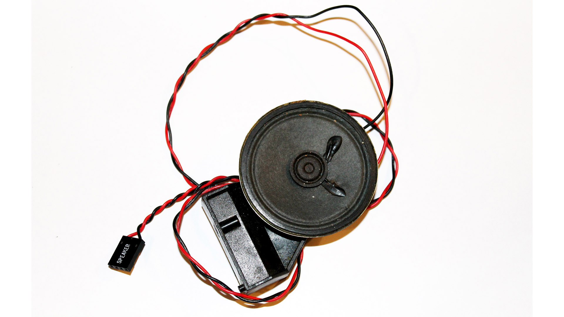
Next, locate your case’s front panel connectors. Many of them will be redundant on this system, but the power switch, power LED and reset switches can all be connected – check your motherboard manual to find the location of the headers, and plug them in now. This area is also where you’ll be able to attach an internal PC speaker, usually with a 4-pin header (with two wires).
Even if you have a sound card, it’s worth having a PC speaker to identify error beeps, and for sound in some older games – if your case doesn’t have a speaker, you can pick up a small one for £2 from Amazon, which will do the job fine.
Now offer up the motherboard to the case, plug in the 20-pin ATX power connector, gently push the motherboard into its I/O backplate at a slight diagonal (being careful not to scrape it on the standoffs below), then gently lower it down and screw it into the standoffs.
How to set IDE jumpers
Next comes storage, which sadly isn’t as simple as just plugging in the cables and screwing the drives into the case. IDE cables usually have two connectors, for connecting two drives to one IDE channel, in what was then (politically incorrectly) called ‘master and slave’ configuration – you wanted your faster drive (such as your boot hard drive) to be the master, and slower drive (such as a CD-ROM) to be the slave.
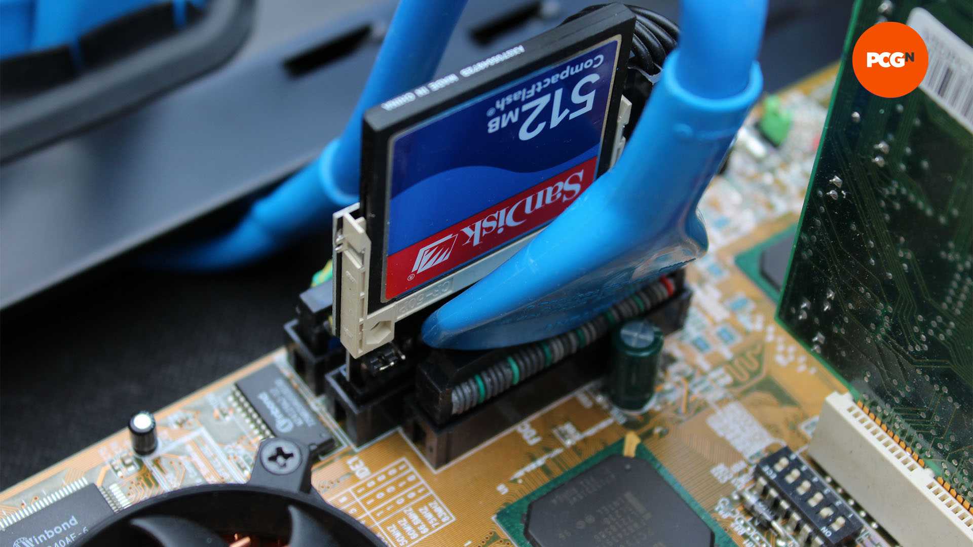
In our case, we’re using two separate IDE channels for each of our IDE drives, rather than connecting more than one drive to the same channel, but we still need to set up our drives properly. On the back of an IDE CD-ROM or hard drive (and on our CompactFlash PCB) will be a jumper, which can be switched to M, S or CS, with the latter standing for ‘cable select’, although we recommend using the ‘master’ or ‘slave’ options for certainty.
Set this to ‘M’, unless you’re running two drives on one cable, in which case set the faster drive to ‘M’ and the slower drive to ‘S’. If you don’t do this properly – for example, by putting two ‘master’ drives on one cable – the system may not boot. You can then connect your IDE cables.
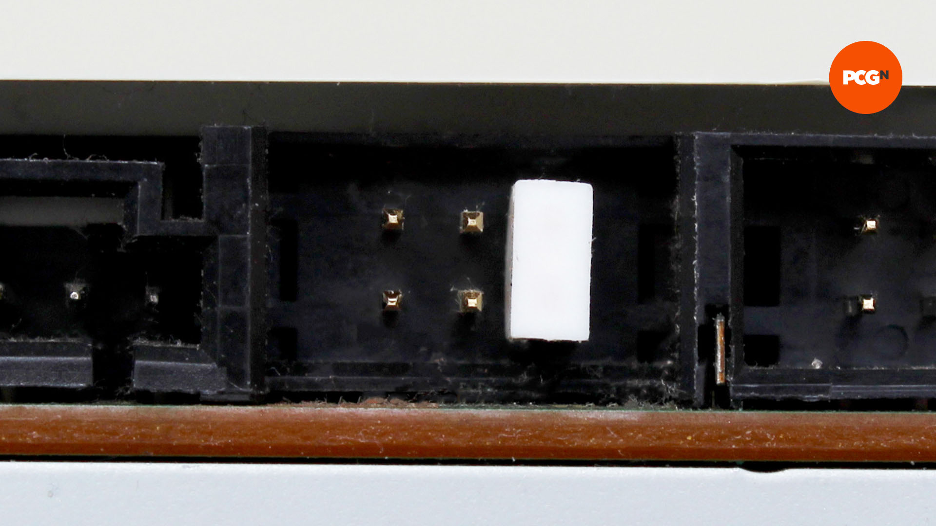
There will be two plugs with a short length of cable between them, and a longer cable going down to a third plug. The latter plugs into your motherboard’s IDE socket (a notch means it can only be fitted the right way around), and the top plug goes into your drive. If you’re connecting two drives, the ‘top’ plug goes to the ‘master’ drive and the second plug goes to the ‘slave’ drive.
You can route your IDE cables around the back using your cable-routing holes, and you’ll also need to route power cables to your drives from your PSU, using Molex or 4-pin floppy connectors. Next comes the CompactFlash adaptor, if you’re using one. You just need to make sure its jumper is set to ‘master’, hook up a floppy power connector and plug it into your motherboard’s primary IDE channel socket.
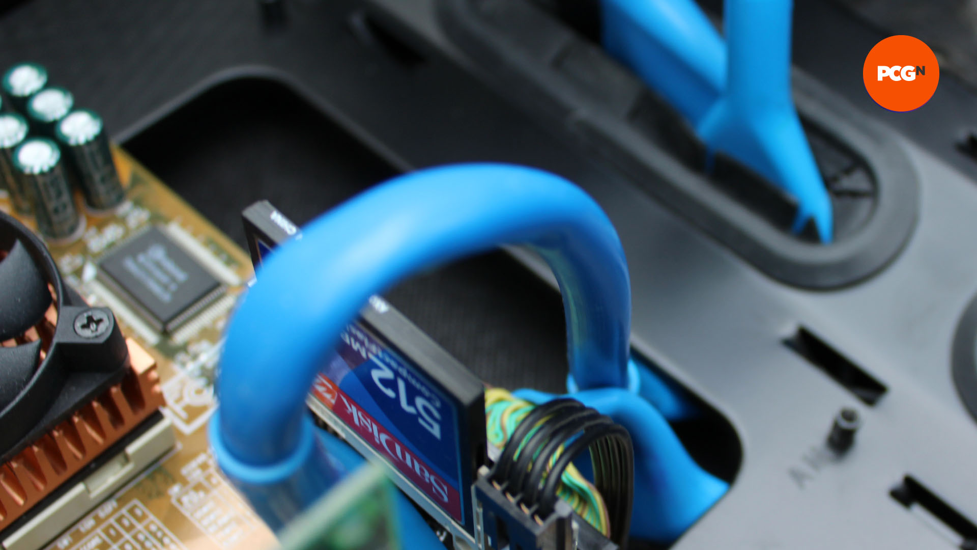
Meanwhile, your floppy drive needs to be connected to your motherboard’s floppy controller socket, which looks like a slightly smaller IDE socket. Sadly, most floppy drives don’t have a notch to make sure you can only install the cable the right way around, but it’s not disastrous if you get it wrong. If you turn on your system, and the floppy drive light is on permanently, and the floppy drive isn’t detected, then the cable is the wrong way around – you just need to turn it round the right way.
Install your PCI and ISA cards
Finally, slot your graphics card and sound card into place – put the graphics card in the top PCI slot, and the sound card in one of the bottom ISA slots. ISA cards have the PCB on the other side of the backplate from PCI cards, with their chips facing the top of the case, but you fit them in the same way. Slot them in place, and secure their backplates with your case’s screws.
Boot up your retro gaming PC
All your hardware is now basically installed – the final step is to plug in your keyboard, mouse, mains cable and VGA cable and start it up. Your BIOS should be set to boot from the floppy drive (A) by default, but you’ll be able to change the boot priorities in the BIOS by pressing Del when your system starts up. The next step is to insert your DOS boot disk and boot up your system.
That’s a wrap for our guide on how to build a DOS gaming PC. If you’re looking to assemble a more modern system, make sure you check out our full best gaming CPU guide, as well as our best graphics card guide, where we run you through all your best options to suit a range of budgets.
